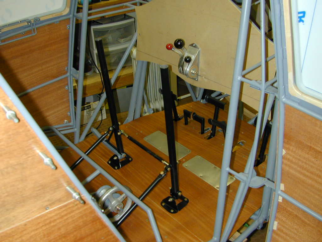
The rudder pedals needed a lot of work. They were bent from the accident. I was able to use about half of the original assembly and had to make the rest.

This assembly bent and Shawn at Jarrell Aircraft Fabrication was able to work some magic and get it all strightened out and reusable. All parts were bead blasted, epoxy primed and painted.

I hammer formed the pedal tops out of steel sheet. They came out just like the originals.


Passenger control stick attach bracket and pivot assembly.


Needed to fabricate a new aileron control rod, this is the long one from the bottom of the pilot’s control stick up to the aileron bellcrank mounted on the front spar. The original one was bent in the accident and no longer usable.

Fabrication of the long aileron control rod that goes from the bottom of the pilot’s control stick up to the aileron bell crank mounted on the front spar. I prototyped the shape using a piece of aluminum angle, show on the right hand side in this picture. Using the shrinker and the stretcher allowed me to easily shape the gentle curves required: the one at the lower end to give me a as much side leg room as possible and the one at the top to clear the fuselage frame above the window.
I then bent the 4130 steel tube to that shape as seen on the left. In this picture there is extra length top and bottom — necessary to make the bends.
I actually made up two of these control rods. One has the original linkages; a fork at the bottom and steel tube at the top. The second one has Heim rod end bearings. Both are the same shape, length and are easily interchanged. The drawing for the long aileron pushrod, linked above, is for the Model 90A, and calls for a lower half of 7/8” OD x 0.035” wall, and an upper half of 5/8” OD x 0.065” wall, spliced in the middle. My original rod, along with Norman Cowell’s Model 110 NC533W, and Gary Gulliat’s Model 90 NC538W all have 5/8” rod the entire length.
No comments:
Post a Comment