
The very front of the Monocoupe 110 fuselage is defined by the dishpan ring. This is a 1/2” OD 4130 steel tube which stands off of the Edmundson-Owl motor mount ring and to which the outer edge of the dishpan attaches and the forward edge of the boot cowl. The dimensions and shape of this piece are defined by a Monocoupe drawing. This piece has a different shape than what you will find on a Model 90A fuselage. On a Model 90A, with Lambert or Warner 145 conversion, the dishpan ring is round. On the Model 110, the two bottom corners ar emoved or “bumped out”, almost 2” to provide clearance for the Monocoupe 110 fuselage forward lower longerons. I made a pattern on paper using the Monocoupe drawing, and then formed the tube to that shape.

The picture to the left does a good job of highlighting the challenge. A round dishpan, as you will find on a 90A, (in this picture shown by a piece of MDF) just won’t provide adequate clearance for the boot cowl around those lower longeron forward corners.

If you look closely at N15E, a clipwing in the EAA museum, which is built on a Monocoupe 110 fuselage, you can see that the boot cowl has “blisters” added to provide the necessary clearance over those lower corners. On N501W, Jim had to put some small bumps in the boot cowl to provide clearance.
What all of this means is that the bottom boot cowl skins need a lot of shape in them to flow smoothly from the dishpan ring to the fuselage bottom and sides. It simply is not possible to use a flat sheet of aluminum and have it fit down there. With the dishpan ring shaped per the Monocoupe 110 print, the next challenge was to get it centered around the Edmundson Owl motor mount ring with the appropriate set back. The 110 Special (with Warner 145) print calls for a 5 3/8” set back from the motor mounting surface. The print is based on the original hard mount and not the Owl mount. So, I had to mock everything up, with the Owl motor mount brackets in place and determine the set back. The series of pictures below, show how this was jigged.


The Owl motor mount brackets were fabricated and installed on steel bushings. I cut an 18” diameter circle out of 3/4” MDF and was able to match drill motor mount holes using and old fuselage from N501W, when it had a Warner 145, which happens to be hanging in my hangar. Jigged the fuselage level, and with the motor mount template in place, determined the exact back set for the dishpan ring, and got it clamped in space where it needed to be. Then fabricated the steel tube stand offs and JB welded everything in place temporarily so I could then see how it looked. This whole assembly had to line up with the windshield hoop and the fuselage former tubes forward of the doors.

Once I got everything lined up and was happy with it, then I was able to fabricate poster board patterns for the boot cowl skins. Lots of iterations on this until I got patterns I was happy with.

The dishpan was made out of stainless steel. I made it in sections — easier to shape, hammer formed a flange on the inner diameter edge to provide rigidity and form shaped the outer diameter edge in place with the dishpan tube. Bottom center section of dishpan is removable—mostly because I don’t have the engine back yet from Alan and I know that down in this area there is the induction system, throttle and mixture cables, etc.

Top skin is two pieces, seamed in the middle with a doubler and flush rivits. This was due to the size of AL sheets and shipping. A small amount of shape went into the top piece using the English Wheel, although this is probably a piece that could have just been wrapped around. The windshield hoop and dishpan ring have tabs welded for screw attachment. Doors are hinged and fasten on the bottom with camlocs.

The bottom piece has much more shape in it than is seen in the picture. It clears the lower longeron corners without any blisters or bumps. The entire bottom piece is removable for maintenance providing easy access to the area under the floorboards where the hydraulic brake cylinders are mounted horizontally. In some of the pictures, the English Wheel tracking marks are evident.

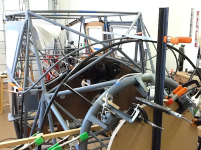
You can really see the “bumped out” lower corners of the 110.
No comments:
Post a Comment